GRE Tunnels
At this point, it is not possible to automatically create links between nodes of the CityLab testbed using the JFed interface. Fixing this issue is at the very top of our TODO list, but because of external factors beyond our control we are currently not able to commit to any particular deadline.
As a workaround it is possible to manually create links between nodes, once the test is running. This is done by establishing GRE-tunnels between the nodes over the management interface. Once a tunnel has been established, it can be used just like any other Ethernet-interface except that it has a slightly lower MTU.
A number of scripts are provided to make this as easy as possible to create and manage these tunnels.
Preparation
Before any tunnels can be created, the scripts first need to be installed on every node. This can be done by running the following one-liner:
wget -O- https://doc.lab.cityofthings.eu/w/images/9/93/Gre-utils.tar.gz | sudo tar -C /usr/local/ -zxvf -
This command will
- Download the Gre-utils.tar.gz archive
- Install the scripts in
/usr/local
Creating a link between two nodes
A simple GRE tunnel can be created by running the gre_add_tunnel script on both nodes.
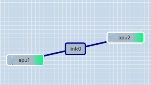
The setup shown in the example on the right can be created as follows:
- On apu1 run:
sudo gre_add_tunnel -c 192.168.0.1/24 link0 apu2 - On apu2 run:
sudo gre_add_tunnel -c 192.168.0.2/24 link0 apu1
In the above commands link0 is the name of the interface to create and apuX is the host to create a tunnel to. The optional -c flag can be used to automatically configure an IPv4-address on the newly created interface.
To allow the node names configured in JFed to be used to configure GRE tunnels, the gre_add_tunnel script tries to behave somewhat intelligently when resolving hostnames:
- If the specified host is a Fully Qualified Domain Name (i.e: it contains a '.'), a regular DNS query is performed
- If the specified host is a simple hostname (no '.' in the hostname), the
gre_add_tunnelscript first tries to resolve the specified host to a node name specified in JFed. If this fails, the IP-address of the host is resolved using a normal DNS query. - If the specified host is a valid IPv4 address, no DNS-resolution is performed.
Once the GRE tunnel is created, it can be used just like any other Ethernet interface, except that the MTU is a bit lower than normal.
Removing the tunnel is done using the gre_del_tunnel script.
To remove the tunnels created above for example, the following command would have to be run on each node:
sudo gre_del_tunnel link0
Creating a link between three or more nodes
Creating a link between more than two nodes is (slightly) more complicated since GRE only allows Point-to-Point tunnels to be created. To work around this, GRE Tunnels are created from one 'central' node to all other nodes on the link. These GRE Tunnels are then 'bridged' together on the central node to form a shared subnet. Such a 'GRE Bridge' can easily be created using the gre_add_bridge script.
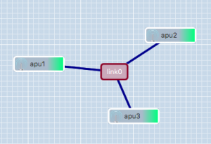
The 3-node setup shown in the example on the right can be created as follows:
- On apu1' run:
sudo gre_add_bridge -c 192.168.0.1/24 link0 apu2 apu3
As for thegre_add_tunnelscript,link0is the name of the interface to create and the code>-c flag can optionally be used to configure an IPv4 address on the interface. The remaining parameters, in this caseapu2andapu3are the hosts to connect to. The resolution of these hostnames to IP-addresses is done in exactly the same way as for thegre_add_tunnelscript.
- On apu2 run:
sudo gre_add_tunnel -c 192.168.0.2/24 link0 apu1 - On apu3 run:
sudo gre_add_tunnel -c 192.168.0.3/24 link0 apu1
- On apu2 run:
In this case apu1 is used as the central node and apu2 and apu3 connect to it in exactly the same way as in the two node scenario.
Once the 'GRE Bridge' has been created it can be used just like any other linux bridge. Additional interfaces can be added/removed using the brctl command. The bridge's stastus can be queried using the brctl show command:
 user@apu1:~$ brctl show link0
 bridge name	bridge id		STP enabled	interfaces
 link0		8000.a2b74a105a76	no		link0_gre_0
 							link0_gre_1
In the above output, the link0_gre_x interfaces are the GRE tunnels to the individual nodes.
Removing the 'GRE Bridge' is done using the gre_del_bridge_script. It is highly recommended to use this script to remove the bridge (rather than the brctl command) as this script not only removes the bridge itself, but also cleans up the GRE-tunnels to the individual nodes.
To remove the bridge created in the above example the following command would have to be run
- On apu1:
sudo gre_del_bridge link0
Once the 'GRE Bridge' has been removed, the GRE-Tunnels on the other nodes also need to be cleaned up. This is done in exactly the same way as in the two node scenario:
sudo gre_del_tunnel link0
Limitations
GRE Tunnels are identified solely on the source and destination IP-address of the encapsulating packet. That means that it is not possible to establish two independent tunnels between the same two nodes at the same time.
For the two node scenario, this means that only a single link can be created between two nodes.
For the mutliple nodes scenario, a node can participate in multiple links as long as:
- each link uses a different 'central node'
- each 'central node' is only part of one link at the same time
It should be noted however, that GRE Tunnels can be used in combination with VLAN-tagging, so if you really need to create multiple links between two nodes, it is possible to do so, but this is not something that can be done using the scripts provided here.

