Difference between revisions of "GRE Tunnels"
| Line 181: | Line 181: | ||
=== Creating a link between two nodes === | === Creating a link between two nodes === | ||
| − | [[File:Jfed-multisite-link-2-nodes.png|thumb|right|A 'simple' multi-site link with two nodes.]] | + | [[File:Jfed-multisite-link-2-nodes.png|thumb|right|A 'simple' multi-site link with two nodes. 'citynode1' is a node of the Citylab testbed. 'vwallnode1' is a node of the Virtual Wall testbed.]] |
A point-to-point (E)GRE tunnel can be created using the <code>gre_add_tunnel</code> script on both nodes. | A point-to-point (E)GRE tunnel can be created using the <code>gre_add_tunnel</code> script on both nodes. | ||
Revision as of 12:28, 11 August 2021
At this point, the CityLab testbed only has limited support for automatically creating links between nodes using the JFed interface. Standard IP-in-IP GRE Tunnels and Ethernet-in-IP GRE Tunnels (gre-tunnel and egre-tunnel links in JFed) are supported. Adding support native Ethernet links (lan links in JFed) is on our TODO list. Since both 'gre' and 'egre' tunnels are point-to-point tunnels it is currently not (yet) possible to create a JFed-link with more than two connected nodes. As a workaround it is possible to bridge multiple 'egre'-tunnels together into a single (tunneled) L2-network once the test has started.
This page provides a quick How-To guide on how to create standard 'gre' or 'egre-tunnels' in JFed and then explains how to manually set up and bridge egre-tunnels manually (after the test has started).
Creating Links between nodes through the JFed interface
Setting up links
Creating Links between nodes through the JFed interface is very straightforward and can be done as follows:
- Start JFed, click on 'New' and drag in two wireless nodes. For this tutorial we'll assume that these nodes are called apu1 and apu2
- Edit the node properties so both nodes are sourced from the City of Things Antwerp testbed. (By default Wilab2 is used).
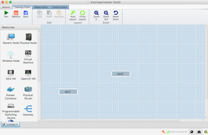
- Drag a line from apu1 to apu2. A link element connecting the two nodes is automatically created.
- If you are using JFed GUI 5.9 or above, link type of the link will already be set to 'gre'. (This is shown between braces behind the name of the link).
If this is not the case, or you would like to create an 'egre'-link instead, the link-type will need to be manually configured:
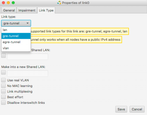
- Right-click on the link-element, Click on Configure Link and select the Link Type-tab in the options window.
- Change the link-type to 'gre-tunnel' or 'egre-tunnel' in the drop-down menu. If you select 'gre-tunnel' an IP-in-IP tunnel will be created, if you select 'egre-tunnel' an Ehternet-in-IP tunnel will be created.
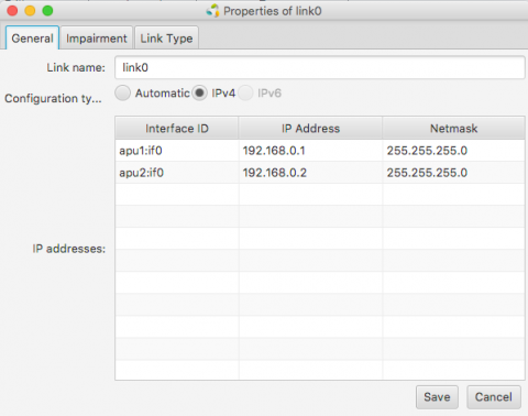
- JFed will automatically configure an IP-address on the tunnel interface for both nodes. optionally you can modify these IP-addresses in the General tab of the Link options-window


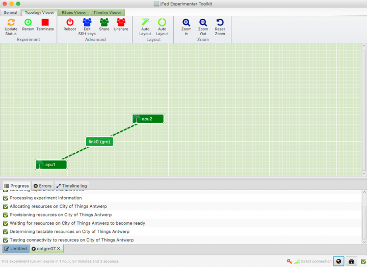
- Click 'Run' to start your slice. When all nodes are green, your experiment has started and the GRE-tunnel between the two nodes has been configured.

- SSH into the apu1 node.
- Run
ifconfig link02to verify that the GRE-tunnel has been created
user@apu1:~$ ifconfig link02
link02    Link encap:UNSPEC  HWaddr 8F-81-55-10-00-00-80-3F-00-00-00-00-00-00-00-00
          inet addr:192.168.0.1  P-t-P:192.168.0.1  Mask:255.255.255.0
          inet6 addr: fe80::200:5efe:8f81:5510/64 Scope:Link
          UP POINTOPOINT RUNNING NOARP  MTU:1434  Metric:1
          RX packets:2 errors:0 dropped:0 overruns:0 frame:0
          TX packets:3 errors:0 dropped:0 overruns:0 carrier:0
          collisions:0 txqueuelen:1
          RX bytes:112 (112.0 B)  TX bytes:168 (168.0 B)
- Ping the apu2-tunnel enpoint by running
ping -c 4 <ip>where<ip>is the IP-address configured for the tunnel endpoint on apu2. If you have not changed this, this is192.168.0.2
user@apu1:~$ ping -c 4 192.168.0.2
PING 192.168.0.2 (192.168.0.2) 56(84) bytes of data.
64 bytes from 192.168.0.2: icmp_seq=1 ttl=64 time=2.21 ms
64 bytes from 192.168.0.2: icmp_seq=2 ttl=64 time=1.60 ms
64 bytes from 192.168.0.2: icmp_seq=3 ttl=64 time=1.46 ms
64 bytes from 192.168.0.2: icmp_seq=4 ttl=64 time=1.51 ms

--- 192.168.0.2 ping statistics ---
4 packets transmitted, 4 received, 0% packet loss, time 3004ms
rtt min/avg/max/mdev = 1.464/1.699/2.218/0.303 ms
Limitations
No more than 2 nodes per link
It is not possible to create (E)GRE-links with more than two nodes. The JFed GUI does allow additional nodes to be added to the link, but when the test is started the link will only exist on two nodes. This limitation is caused by the fact that the GRE-protocol only supports point-to-point tunnels. It is possible to set up and bridge multiple egre-tunnels, but this cannot be done through the JFed interface.
EGRE-tunnels only work with 'CoT' disk images
To enable support for 'egre-tunnel' links, a few tweaks had to be made to the 'client-side' emulab-tools installed in the testbed disk images. Since these tweaks are not (yet) incorporated in the upstream emulab-code base, they are also not present in the many emulab-images used around the world.
We have added these tweaks to the 'CoT' disk-images of the CityLab testbed (see Disk Images), so if you want to use egre-links you must use a 'CoT' disk image.
(E)GRE-tunnels between nodes of different testbeds cannot be created via JFed
Even at the best of times, creating links between nodes of different testbeds is an 'experimental feature' at best. While it is perfectly possible to set up GRE and EGRE tunnels between nodes of different testbeds, it is currently not possible to do so through the JFed interface.
Link impairment on GRE Tunnels cannot be configured through the JFed GUI
The way JFed normally adds impairment to a link is by adding a so-called 'impairment node' in between the nodes of a link to change the properties of the traffic flowing over the link. This mechanism however only works with ethernet interfaces and not with GRE Tunnels. That being said: it is possible to add link impairment to GRE tunnels manually. How to do so is explained below.
Manually setting up EGRE-tunnels
Important: although it is possible to manually set up GRE-tunnels it is much easier to do so through the JFed-interface. The only reason for creating them manually is to create a 'link' between more than two nodes or to create links with nodes of another testbed (both of which are currently not supported through JFed)
A number of scripts are provided to make it as easy as possible to create and manage EGRE-tunnels. Before any EGRE-tunnels can be created, these scripts first need to be installed on every node. This can be done by running the following one-liner:
wget -O- https://doc.lab.cityofthings.eu/w/images/9/93/Gre-utils.tar.gz | sudo tar -C /usr/local/ -zxvf -
This command will
- Download the Gre-utils.tar.gz archive
- Install the scripts in
/usr/local
Creating a link between two nodes

A simple GRE tunnel can be created by running the gre_add_tunnel script on both nodes.
The setup shown in the example on the right can be created as follows:
- On apu1 run:
sudo gre_add_tunnel -c 192.168.0.1/24 link0 apu2 - On apu2 run:
sudo gre_add_tunnel -c 192.168.0.2/24 link0 apu1
In the above commands link0 is the name of the interface to create and apuX is the host to create a tunnel to. The optional -c flag can be used to automatically configure an IPv4-address on the newly created interface.
To allow the node names configured in JFed to be used to configure GRE tunnels, the gre_add_tunnel script tries to behave somewhat intelligently when resolving hostnames:
- If the specified host is a Fully Qualified Domain Name (i.e: it contains a '.'), a regular DNS query is performed
- If the specified host is a simple hostname (no '.' in the hostname), the
gre_add_tunnelscript first tries to resolve the specified host to a node name specified in JFed. If this fails, the IP-address of the host is resolved using a normal DNS query. - If the specified host is a valid IPv4 address, no DNS-resolution is performed.
Once the GRE tunnel is created, it can be used just like any other Ethernet interface, except that the MTU is a bit lower than normal.
Removing the tunnel is done using the gre_del_tunnel script.
To remove the tunnels created above for example, the following command would have to be run on each node:
sudo gre_del_tunnel link0
Creating a link between three or more nodes

Creating a link between more than two nodes is (slightly) more complicated since GRE only allows Point-to-Point tunnels to be created. To work around this, GRE Tunnels are created from one 'central' node to all other nodes on the link. These GRE Tunnels are then 'bridged' together on the central node to form a shared subnet. Such a 'GRE Bridge' can easily be created using the gre_add_bridge script.
The 3-node setup shown in the example on the right can be created as follows:
- On apu1 run:
sudo gre_add_bridge -c 192.168.0.1/24 link0 apu2 apu3
As for thegre_add_tunnelscript,link0is the name of the interface to create and the-cflag can optionally be used to configure an IPv4 address on the interface. The remaining parameters, in this caseapu2andapu3are the hosts to connect to. The resolution of these hostnames to IP-addresses is done in exactly the same way as for thegre_add_tunnelscript.
- On apu2 run:
sudo gre_add_tunnel -c 192.168.0.2/24 link0 apu1 - On apu3 run:
sudo gre_add_tunnel -c 192.168.0.3/24 link0 apu1
- On apu2 run:
In this case apu1 is used as the central node and apu2 and apu3 connect to it in exactly the same way as in the two node scenario.
Once the 'GRE Bridge' has been created it can be used just like any other linux bridge. Additional interfaces can be added/removed using the brctl command. The bridge's stastus can be queried using the brctl show command:
 user@apu1:~$ brctl show link0
 bridge name	bridge id		STP enabled	interfaces
 link0		8000.a2b74a105a76	no		link0_gre_0
 							link0_gre_1
In the above output, the link0_gre_x interfaces are the GRE tunnels to the individual nodes.
Removing the 'GRE Bridge' is done using the gre_del_bridge_script. It is highly recommended to use this script to remove the bridge (rather than the brctl command) as this script not only removes the bridge itself, but also cleans up the GRE-tunnels to the individual nodes.
To remove the bridge created in the above example the following command would have to be run
- On apu1:
sudo gre_del_bridge link0
Once the 'GRE Bridge' has been removed, the GRE-Tunnels on the other nodes also need to be cleaned up. This is done in exactly the same way as in the two node scenario:
sudo gre_del_tunnel link0
Limitations
Single tunnel between two nodes
GRE Tunnels are identified solely on the source and destination IP-address of the encapsulating packet. That means that it is not possible to establish two independent tunnels between the same two nodes at the same time.
For the two node scenario, this means that only a single link can be created between two nodes.
For the mutliple nodes scenario, a node can participate in multiple links as long as:
- each link uses a different 'central node'
- each 'central node' is only part of one link at the same time
It should be noted however, that GRE Tunnels can be used in combination with VLAN-tagging, so if you really need to create multiple links between two nodes, you can do so by defining multiple VLANs on the GRE tunnel interface. This however is not something that can be done using the scripts provided here.
Reduced MTU
Using a GRE Tunnel incurs an overhead of 38 bytes. This is because the original Ethernet packet needs to be prefixed with an additional IP- and Ethernet-header in order to send it to the other tunnel endpoint. To prevent fragmentation, the linux kernel automatically reduces the MTU of the GRE-interface. As a result, the MTU inside the tunnel is 38 bytes lower than the MTU outside the tunnel.
Except for a small decrease in performance this usually is not that big of a problem, with one notable exception. When, for instance, a WiFi AP-interface is bridged to a GRE Tunnel, the MTU is set to the smallest MTU of the 'slave' interfaces (in this case the GRE-tunnel). This lower MTU however is not automagically communicated to the connected WiFi clients and as a result these clients may still send packets that are larger than the MTU of the bridge. Since these packets are subsequently dropped by the linux bridge, this can lead to all sorts of nasty problems. The most common of which are dropped UDP packets and TCP sessions seem to work fine and then suddenly hang when more than a few bytes at a time are sent over them.
To resolve this issue the MTU of the other WiFi clients should be reduced to the MTU of the linux bridge. When static IP-addresses are used, this can easily be done using the ip link command:
ip link set mtu <mtu> dev <device>
If DHCP is used, the lower MTU should be advertised by the DHCP server.
Setting up (E)GRE-Tunnels Citylab and the Virtual Wall
At this point it is not possible to set up 'multi-site' (e)GRE tunnels through the JFed interface, but it is possible to do so manually after the test has started. The process of doing so is very similar to manually creating EGRE-Tunnels within the citylab testbed itself, but the following caveats need to be taken into account:
- Setting up GRE Tunnels between nodes of different testbeds requires both endpoints to have a routable (i.e. public) IPv4 or IPv6 address and for GRE-traffic to be allowed by the firewall/router through which the nodes are connected to the internet. While all nodes of the citylab testbed meet the above requirement, this may not necessarily be the case for nodes of other testbeds.
- The MTU of the created link needs to be set manually. Otherwise you will most likely encounter MTU-mismatch issues given that, by default, the MTU of the created tunnel is calculated from the MTU of the uplink interface, and that not all testbeds use the same MTU on their uplink interface.
- GRE tunnels are not encrypted. Any data you send over them is sent plain-text over the internet so make sure not to send any sensitive data over them without adding encryption in some other way. If you need a tunnel which encrypts the traffic as well, OpenVPN is most likely a better solution.
The remainder of this section explains how to set up 'multi-site' (e)gre tunnels. We specifically focus on setting up GRE tunnels between Citylab and the Wall, but setting up GRE tunnels to other testbeds should be very similar.
Prerequisites
- Make sure that all nodes involved are running at least Ubuntu 16.04 (EGRE tunnels are not supported in Ubuntu 14.04 and before). For citylab nodes this is the case by default, but for the nodes on the virtual wall you will have to explicitly specify a different disk image when you set up the experiment as that testbed uses 'Ubuntu 14.04' by default.
- Setting up multi-site (e)gre tunnels is done with the same 'helper scripts' as used before. Before setting up the tunnels themselves, these scripts need to be installed on every node. This can be done using the following one-liner:
wget -O- https://doc.lab.cityofthings.eu/w/images/9/93/Gre-utils.tar.gz | sudo tar -C /usr/local/ -zxvf -
Creating a link between two nodes

A point-to-point (E)GRE tunnel can be created using the gre_add_tunnel script on both nodes.
The setup in the example on the right can be created as follows:
- Run the
hostnamecommand on both hosts to learn their fully qualified domain names (FQDNs). E.g:root@citynode1:~# hostname citynode1.gretest.wall2-ilabt-iminds-be.lab.cityofthings.eu
root@vwallnode1:~# hostname
vwallnode1.gretest.wall2-ilabt-iminds-be.wall2.ilabt.iminds.be
- As shown in the examples above the FQDNs of the nodes depends not only on the hostname configured in JFed but also on the name of the experiment, project and the testbed the node belongs to. Therefore yuo will almost certainly need to use different FQDNs than the ones listed above
- Create the EGRE tunnel itself:
- On citynode1 run:
sudo gre_add_tunnel -c 192.168.0.1/24 -m 1400 -6 link0 <fqdn_of_vwallnode1> - On vwallnode1 run:
sudo gre_add_tunnel -c 192.168.0.1/24 -m 1400 -6 link0 <fqdn_of_citynode1>
- On citynode1 run:
The gre_add_tunnel commands shown above are very similar to the ones used to set up an EGRE-tunnel between citylab nodes, but there are a few important differences:
- Rather than only specifying the hostname of the other endpoint, the full FQDN needs to be specified
- The
-mflag is added to manually set the MTU on the link. As explained before, this is needed to prevent MTU-mismatch issues. In this specific example an MTU of1400bytes is specified since it provides enough headroom for multiple encapsulation headers and is 'good enough' for an initial test. For optimal performance however, the MTU should be set tomin(uplink MTU of all nodes involved) - <GRE Overhead>(38 bytes). - The
-6flag is added to instruct thegre_add_tunnelto create a 'GRE-over-IPv6' rather than a 'GRE-over-IPv4' tunnel. The reason for using IPv6 in this case is that the nodes of the virtual wall testbed don't have a public IPv4 address.
Instead of specifying the FQDNs of the nodes, it would also have been possible to specify the public IP address of the node directly but this is more cumbersome and error prone (especially when using IPv6). Once the tunnel has been created it can be used just like any regular Ethernet interface except that, once again, the MTU is somewhat lower.
As before, removing the tunnels is done using the gre_del_tunnel script:
sudo gre_del_tunnel link0
Creating a link between three or more nodes

As with GRE links between citylab nodes, setting up a GRE-link with more than two nodes is done by:
- Creating GRE tunnels from all nodes to a 'central' node
- Bridging all of these tunnels together to create a single shared subnet.
When such an 'overlay subnet' spans multiple testbeds however, it is important to select the 'central node' very carefully. Consider for example the topology shown on the right. In this case a link is created to which two nodes of the citylab testbed and a single node of the virtual wall are connected. If, in this case, vwallnode1 were to be selected as the 'central' node, then all traffic between citynode1 and citynode2 would be sent over the virtual wall testbed unnecessarily. If on the other hand citynode1 or citynode2 is used as a 'central' node, then this problem is avoided.
Setting up Link impairment on GRE Tunnels
While it is not possible to configure link-impairment on GRE tunnels via the JFed interface, it is possible to do so manually once the test has started. This not only works for links created by JFed but also for links created manually.
Adding impairment to a link is done by running the following command on each node connected to the GRE-tunnel:
sudo tc qdisc add dev <link> root netem loss random <loss_percentage>% rate <data_rate> delay <delay_in_micro_seconds>
In this command:
<link>is the name of the gre tunnel interface<loss_percentage>is the percent of packets to be randomly dropped<data_rate>is the data rate limit to impose on the link (e.g 10mbit, 20kbit, ...)<delay_in_micro_seconds>is the delay (in microseconds) to add to packets sent from the host. (So: to add a 5ms delay you need to specify 5000)
As an example, the following command adds a 20% loss, a maximum data rate of 35mbit and a 7.5ms delay to link0
sudo tc qdisc add dev link0 root netem loss random 20% rate 35mbit delay 7500
Important: The link impairment configured with the above command only affects packet that are sent from the host. Received packets are unaffected. Therefore it is imperative that you configure the same link impairment settings on both nodes connected to the GRE tunnel.
Removing link impairment on a link is done by running the following command
sudo tc qdisc add dev <link> root netem
To change the impairment settings on a link, you first need to remove the link impairment all together and then add it again with the new settings.
More information on the 'netem' traffic control queueing discipline can be found here: https://www.systutorials.com/docs/linux/man/8-tc-netem/