Node Specifications: Difference between revisions
No edit summary |
|||
| Line 7: | Line 7: | ||
* Dash7 on 433MHz and 868MHz | * Dash7 on 433MHz and 868MHz | ||
* LoRaWAN on 868MHz (client only) | * LoRaWAN on 868MHz (client only) | ||
== Node Hardware == | == Node Hardware == | ||
| Line 74: | Line 71: | ||
== Antennas == | == Antennas == | ||
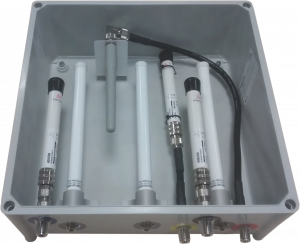
[[File:Node_antennas.png|300px|thumb|right|The antennas of the City of Things experiment nodes]] | |||
Each experiment node is equiped with a number of different antennas (10 in total). These antennas are housed in a separate plastic enclosure to ensure that the placement of the antennas is consistent. | |||
Each radio interface is connected to one or more antennas using low loss coax cable. Depending on the operating frequency of the radio interface, a different type of antenna is used. | |||
* <b>2.4GHz / 5GHz: </b>[http://interline.pl/antennas/HORIZON-LOGIS-DUAL-BAND-MINI Interline Logis Dual-band mini] | |||
* <b>868MHz </b>[[Media:OD840885M2-NM.pdf|OD840886M2-NM Omni Antenna]] | |||
* <b>433MHz: </b>[http://www.farnell.com/datasheets/1696734.pdf RF Solutions ANT-433WM3-SMA] | |||
* | |||
* [http://www.farnell.com/datasheets/1696734.pdf RF Solutions ANT-433WM3-SMA] | |||
Revision as of 09:30, 31 January 2018

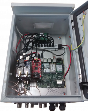
There is currently only a single type of node available in the City of Things testbed. It consists of of an apu2c4 embedded pc with two WiFi interfaces and a number of additional radio modules that are connected through USB. It supports the following wireless technologies out of the box:
- WiFi 802.11ac on 2.4 GHz and 5GHz
- Bluetooth 4.0 (with full BLE support)
- IEEE 802.15.4 on 2.4 GHz and IEEE 802.15.4g 868MHz
- Dash7 on 433MHz and 868MHz
- LoRaWAN on 868MHz (client only)
Node Hardware
Each node uses a PCEngines apu2c4 board as a central controller. This board is equipped with the following hardware:
- CPU: AMD GX-412TC 1GHz Quad-core CPU (onboard)
- Memory: 4GB DDR3-1333 MHz (onboard)
- Storage: 240GB Samsung EVO 850 SSD (mSATA)
The apu2c4 is also equipped with the following WiFi cards:
- Atheros (ath10k) QCA9880 Chipset
- Supports IEEE 802.11 a/b/g/n/ac
- Operates on both 2.4GHz and 5GHz
- Connected to three dual-band antennas (3x3 MIMO is supported).
- Intel 7260 Chipset
- Supports WiFi a/b/g/n/ac and Bluetooth 4.0
- Operates on both 2.4GHz and 5GHz (client mode only)
- Connected to two dual-band antennas (2x2 MIMO is supported).
Connected USB Devices
Each experiment node is equipped with a number of embedded wireless devices connected trough USB. These devices usually consist of a microcontroller with either an embedded or an add-on wireless radio. Each device is equipped with a JTAG/SWD-debugger for programming the device. If the device does not have an on-board debugger a standalone JTAG/SWD-debugger is provided for the device. Likewise each device is also equipped with a USB-to-serial converter to allow the device to communicate with the host. As with the JTAG-debugger the device is connected to a standalone USB-to-serial converter if it does not have one onboard.
OpenUSB (IEEE 802.15.4)
The OpenUSB mote consists of an OpenMote-CC2538 connected to an OpenUSB base board. It has the following features:
- MCU: TI CC2538 SoC (32K ram, 512K flash)
- 2.4 GHz radio: IEEE 802.15.4 tranceiver embedded in the MCU
- 868 MHz radio: TI CC1200 general purpose tranceiver (compatible with IEEE 802.15.4g)
Serial & JTAG Interface:
- Serial communication: FT232R USB to serial converter (onboard)
- Debugger: Olimex TMS320-XDS100-V3 (standalone)
Please note that the JTAG debugger is (1) only supported in windows, (2) not required to flash/erase the OpenUSB mote and (3) only present to allow the system administrators to recover bricked OpenUSB motes. Flashing / Erasing the OpenUSB mote is done through the serial port. See the OpenUSB Tutorial for more information.
EZR USB (Dash 7)
The experiment node contains two EZRUSB boards. These boards are identical except that one is equipped with a 433MHz radio front-end and the other one is equipped with an 868MHz radio front-end. These boards have the following features:
- MCU: Leopard Gecko SoC (32K ram, 256K flash)
- Radio: general purpose, Dash7 compatible, 433MHz/868Mhz tranceiver embedded in the MCU
Serial & JTAG Interface:
- Serial communication:FTDI TTL232R USB to serial cable
- Debugger:Olimex ARM-USB-TINY-H (standalone)
Please note that, for security reasons, the USB-port of the EZR USB is not connected to the host. Communication with the EZR USB module is only possible over the serial interface.
EFM32GG+RFM95W (LoRa)
LoRa(WAN) connectivity is provided through a EFM Giant Gecko development board connected to an RFM95W LoRa tranceiver.
- MCU: Silabs EFM32GG990F1024 (128K ram, 1024K flash)
- Radio: RFM95W 868MHz LoRa Tranceiver
Serial & JTAG Interface:
- Serial communication:Sparkfun 232RL USB to serial breakout board (standalone)
- Debugger:JLink Plus (onboard)
Antennas

Each experiment node is equiped with a number of different antennas (10 in total). These antennas are housed in a separate plastic enclosure to ensure that the placement of the antennas is consistent. Each radio interface is connected to one or more antennas using low loss coax cable. Depending on the operating frequency of the radio interface, a different type of antenna is used.
- 2.4GHz / 5GHz: Interline Logis Dual-band mini
- 868MHz OD840886M2-NM Omni Antenna
- 433MHz: RF Solutions ANT-433WM3-SMA